
|
ACTUAL SYSEM SETUP |
2.1 SYSTEM BLOCK DIAGRAM

Figure 2.1: Cylinder lubrication system with Alpha lubricators.
2.2 SYSTEM EXPLANATION
This cylinder lubrication, shown in the figure is based on a lubricator which injects a specific volume of oil into each cylinder for each (or for every second, third, etc.) revolution. The oil fed to the injectors is pressurized by means of Alpha lubricator on each cylinder, equipped with small multi-piston pumps. The amount of oil fed to the injectors can be finely tuned with an adjusting screw, which limits the length of the piston stroke. The cylinder lube oil consumption in ME type engines, with electronic lubricators, has come down to 0.7 gm / BHP hr.
The whole system is controlled by the Cylinder Control Unit (CCU) which calculates the injection frequency on the basis of the engine-speed signal given by the tacho signal and the fuel index.
The cylinder oil can be introduced to the individual cylinder at any piston position but, preferable, when the piston rings are adjacent to the lubricating quills. The computer synchronizes itself at each revolution, when the piston for cylinder No. 1 is at top dead centre. The injection function is controlled by the computer sending an ON/OFF signal to a solenoid valve. The dosage of oil can be adjusted means of an adjustment screw which limits the stroke of the main lubricator piston. After a predetermined time interval, the computer transmits an OFF signal to the solenoid valve, which shuts off the system pressure and opens the return oil system.
The amount of oil injected varies as required, e.g. at load changes, start/stop, or increased engine load. Alternatively, the dosage of oil fed to the individual cylinders can be adjusted by injecting a calibrated amount of oil, a number of times, at a given number of revolutions. A combination of the two systems can also be used. In the event of malfunctioning solenoid valve or transducer, the oil dosage will automatically be increased to the maximum volume. If the oil pressure falls, the computer will start stand-by pump, close down the faulty pump and sets on the alarm. The Alpha cylinder lubricator has demonstrated a reduction of cylinder oil feed rate to 0.3 gm / BHP hr, which on a 50,000 BHP engine, saves US $ 50,000 p.a.
2.3 DESIGN FEATURES AND FUNCTIONS
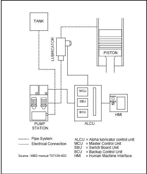
Figure 2.2: Alpha Lubrication Control
A pump station delivers lube oil to the lubricators at 45 bar pressure. The lubricators have a small piston for each lube oil quill in the cylinder liner, and the power for injecting the oil comes from the 45 bar system pressure, acting on a larger common driving piston. Thus, the driving side is a conventional common rail system, whereas the injection side is a high-pressure positive displacement system, thus giving equal amounts of lube oil to each quill and the best possible safety margin against clogging of single lube oil quills.
For the larger bore engines, each cylinder has two lubricators (each serving half of the lube oil quills) and an accumulator, while the small bore engines (with fewer lube oil quills per cylinder) are served by one lubricator per cylinder. The pump station includes two pumps (one operating, the other on stand-by with automatic start up), a filter and coolers.
The lubricator can be delivered for our conventional engines in which case it is controlled by a separate computer unit comprising a main computer, controlling the normal operation, a switchover unit and a (simple) back-up unit. A shaft encoder supplies the necessary timing signal in that case. When used on ‘Intelligent Engines’, these functions are integrated in the engine control computers and their shaft encoders.
The lubrication concept is intermittent lubrication – a relatively large amount of lube oil is injected for every four (or five or six, etc.) revolutions, the actual sequence being determined by the desired dosage in g/bhph. The injection timing is controlled precisely and – by virtue of the high delivery pressure – the lube oil is injected exactly when the piston ring pack is passing the lube oil quills, thus ensuring the best possible utilization of the costly lube oil.
The safety features of this system are as follows:
Ø In this system if one lubricator malfunctions (980-700 mm bore engines), the oil dosage from the other lubricator will be automatically doubled, and an alarm will be given whereas for 600-260 mm bore engines, alarm and slow down ensue.
Ø An inductive sensor in each lubricator monitors the movement of the lubricator piston a signal is sent to the control computer system which has a backup for safety.
2.4 ALPHA LUBRICATOR
2.4.1. Structure of Alpha lubricator
Figure 2.3: Alpha Lubrication Unit
2.4.2 Working principle
Piston ring is considered a kind of wiper. The oil fed to the portion above the piston ring is wiped up by the piston ring to reach the upper portion of the cylinder, and is left at the top dead centre, then is vaporized and degraded in a high temperature atmosphere. On the other hand, the oil fed to the portion beneath the piston ring is wiped down by the piston ring, and a part of the fed oil may be dropped to drain. Not all the fed oil is workless, (if so, the engine will be seized); the oil which was fed above or beneath the piston ring may not significantly contribute to the lubrication.
On the other hand, the oil fed to the portion between the piston rings should be held between the rings to keep the function for a long period.
i) Based on the above-described concept, a new lubrication system was derived to supply maximum volume of oil between the piston rings. The new lubrication system is given by a unit currently called the “Alpha lubricator” which is also the trade name. In this paper, the system is called the “High speed lubricator”.
The high speed lubricator supplies more oil between the piston rings than conventional lubricator by the lubrication system given below.
(1) Volume of cylinder oil for every injection is increased.
(2) Large volume of oil is charged to the oiling pipe at a stroke.
Thus sufficiently increasing the internal pressure of oiling pipe and
(3) The oil is supplied at a correct timing, within a short time, and overriding the internal pressure of cylinder.
A single lubricator unit has five or six plungers, which plungers are driven by a single hydraulic piston. If every cylinder has seven or more lubrication openings, two of the lubricator units are installed.
The hydraulic pressure is controlled by solenoid valves. A portion of the return oil is fed to the plunger barrel via a slit for succeeding oiling cycle. Accordingly, the working oil is the cylinder oil.
The movement of hydraulic piston is monitored by a feedback sensor, a proximity sensor, to confirm the oiling functioning and to watch the oiling timing to automatically adjust the timing.
.
The control is performed by a controller provided with a computer. Both the rotational angle and the pump lack signal are entered in the controller. With the entered information, the oiling volume and the oiling timing are adjusted.
The timing for initiate the oiling action is immediately before the first ring passes through the oil quill. Within a short period until the fourth ring passes, the oil is fed to the cylinder as large volume as possible.
As a result the volume of oil fed in one cycle increases, thus the oil is not fed at every revolution, and intermittent lubrication is given to adjust the oiling volume. The number of oiling cycles is controlled by the computer to give the designed volume as the total.
Figure 2.6 compares the oiling valve having a cylinder in the Alpha lubricator unit with the conventional one. Similar with the conventional type, the oiling valve is a non-return valve. However, the new valve differs from the conventional one at the front nozzle. That is, the oil is sprayed along the cylinder the cylinder wall, or in the horizontal direction, not in the radial direction of the cylinder. Under normal operation, the oil supply is given at the piston passing time so that even a straight nozzle can feed oil to the piston ring and to the ring land. However, at priming and in timer control mode in case of failing in the control computer, the piston is not necessarily comes at the oil quill, and the oil may be injected in air. Therefore, the design is given so as the ejected oil to reach the cylinder wall even when the piston does not reach the oil quill.
2.4.3 Alpha lubrication system
Figure 2.5: Alpha lubrication system.
2.4.4 Design of Oiling valves
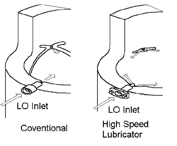
Figure 2.6: Design of oiling valves
2.5 CRITERIA FOR LUBE OIL CONTROL
The principle of the Alpha ACC appears from Figure 2.7
The basic feed rate control should be adjusted in relation to the actual fuel quality and amount being burnt at any given time. The sulphur percentage is a good indicator in relation to wear, and an oil dosage proportional to the sulphur level will give the best overall cylinder condition.
The following two criteria determine the control:
Ø The cylinder oil dosage shall be proportional to the sulphur percentage in the fuel
Ø The cylinder oil dosage shall be proportional to the engine load (i.e. the amount of fuel entering the cylinders).
The implementation of the above two criteria will lead to an optimal cylinder oil dosage, proportional to the amount of sulphur entering the cylinders.
Safe and very lube-economical control is obtained with a basic setting according to the formula:
Basic lube oil setting = 0.34 g/kWh x S%,
With a minimum setting of 0.68 g/kWh, i.e. the setting should be kept constant from 2% sulphur downwards.
Typical saving, depending on sulphur percentage (S%) and average load, will be 25-30% (0.1-0.25 g/kWh) compared to Alpha lubricator in MEP control mode.
The above principle is founded on the observation that the main part of the cylinder liner wear is of a corrosive nature, and the amount of neutralizing alkaline components needed in the cylinder should therefore be proportional to the amount of sulphur (generating sulphurous acids) entering the cylinders.
A minimum cylinder oil dosage is set in order to account for other duties of the cylinder oil (securing sufficient oil film, detergency, etc.).
Figure shows control of cylinder oil dosage proportional to the sulphur percentage in the fuel.
A minimum dosage of 0.5 g / bhph is indicated. This minimum value is preliminary and, given the efficient lubrication achievable with the Alpha Lubricator System, and it is expected to be further reducing this minimum value in the future.
The control according to Figure is based on a standard TBN 70-80 cylinder oil. For operation in long periods with fuels with sulphur content below 1%, it is recommended to change to a cylinder oil with a lower TBN (i.e. TBN 40-50 cylinder oils).
The environmental impact is clearly demonstrated: Owners who wish to operate on ‘green’ fuel (low-sulphur fuel) will, at the same time, have the possibility to operate with ‘green’ cylinder lubrication.
Figure 2.7: Cylinder oil amount proportional to sulphur amount Figure 2.8: Cylinder oil dosage proportional to sulphur percentage in the fuel.
entering the cylinders (the basic principle of Alpha ACC).
2.6 SULPHUR ALGORITHM
The Alpha ACC is implemented with the so-called “sulphur Algorithm”, in the Alpha Lubricator System as in the figure 2.7. In the present version of the Alpha Lubricator System, the crew onboard the vessel inputs the so-called “HMI-setting” based on the sulphur percentage of the fuel used and a conversion table, as in the figure.
This is done by one input on the HMI-panel of the Alpha Lubricator System each time the fuel specification is changed.
Figure 2.9: “The sulphur algorithm” in the Alpha lubricator system